PA31G user interface replacement
This is a short project to replace a burned interface board for PA31G water purifier from Electrolux.
Status:
Work in progressCategory:
EmbeddedPublished at:
28 de novembro de 2023Introduction
Some time ago my water purifier simple decided to stop work. Quickly i took it apart and identified that the interface board was dead.
After figured it, i went to google and started to search for a replacement part but Electrolux website just have filter and lamp replacement parts. Well, in this case the last option is to look in non official sources. I found it in a myriad of sites, but all of them with prices outside reality - in average it's almost R$ 400.
Quickly i discarded the idea of buy a new board and decided to simple wire the pumps to push buttons present in the front trigger. By luck it have 2 switches and then i could wire each pump to one button. This way i can choose between icy (just pressing the left side of trigger), normal (pressing the right side of the trigger) or cold (pressing both at same time).
Doing this reveals another problem, the icy water pump resistance is very low making the current rises a lot. I could see some sparks while turning this pump on and off, while the same doesn't happens with the other water pump.
Original PCB
The PCB is pretty simple, it's a two side board with all connectors for pumps, power, buttons and so on... some leds inside a plastic cage (to not let the light from one led to bleed), the springs used as touch sensors, 2 electrolytic capacitors, the mosfet used to power on the UV lamp ballast and what looks like a JTAG header at PCB top.
The PCB bottom contains a 7805 linear regulator to drop the +24V from power supply to +5V used by the circuit. It also contains the micro-controller, an ULN2803 and another IC that i suppose is used to detect the touches.
Doing a visual inspection i could not find any damaged component. Injecting +24V and tried to measure the output of the linear regulator shows 0V. Trying to replace the 7805 doesn't solve it. My guess is that the pump begins to wear out decreasing the resistance and draws a lot of current. This high current peak is bigger than the maximum ULN2803 can handle, so it get shorted. As this IC is in short, it kills the +5V line.
I attempted to remove the ULN2903 to check if this assumption is right, but i stopped since the PCB begins to become dark brown / black. Maybe someday i can try again to confirm if this is the root cause or not.
Since a new board i very expensive i begin to think, why not create a replacement by myself?
It should not be that complex, right? I mean, the usage is pretty simple as far i remember (to be honest i don't remember some details but as this is just a replacement it's not necessary to mimic exactly all functionalities of the original board).
Features
So, i begin listing all functions it should do:
▪ If natural button is pressed (touched) power on pump1
▪ If icy button is pressed (touched) power on pump2
▪ If cold button is pressed (touched) power on both pumps
▪ Each button have a LED outline
▪ Cycle between low / med and high quantity if qty button is pressed
▪ Detect front lever trigger and power on the pump(s) - I'm not sure it will pour the last temperature used
▪ Keep track how long the user press the buttons to change from manual to automatic mode
▪ Every time water is being poured, light the nozzle LED
▪ Store the quantity of water already poured to know when replace the filter
▪ Check feedback from UV lamp ballast to know when replace the UV lamp
▪ Lit filter / lamp if need to replace
▪ Monitor reset buttons
▪ Keep UV light on while reservoir is refilling
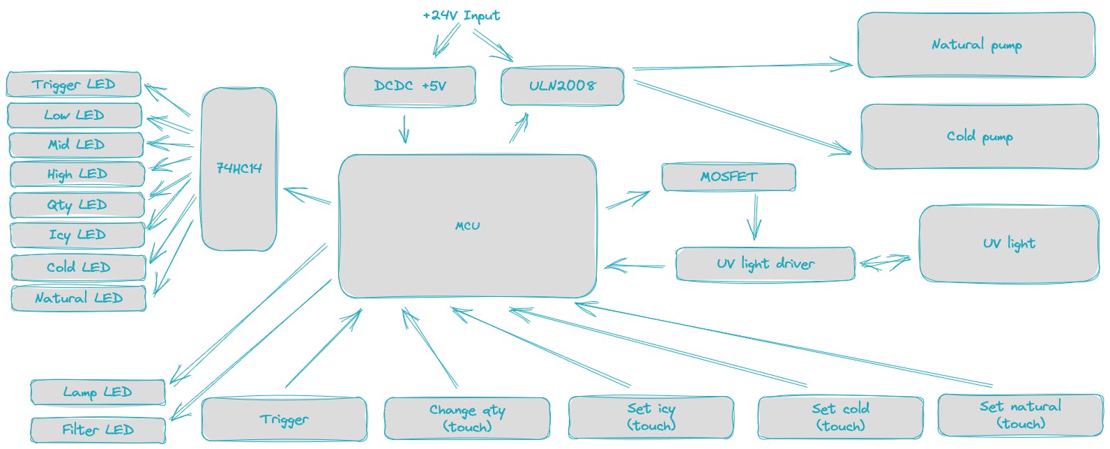
Block diagram
Based on the list above we can begin to sketch some building blocks before go to schematic.
Schematic
As MCU I plan to use an atmega8. It's very popular, cheap and can be found anywhere (and also i have some parts in stock). This microcontroller have up to 23 I/O pins, 8Kb of flash, 1Kb SRAM and also 512 bytes of EEPROM that can be used to store previous state and consumption as well.
[add image]
A 74HC164 will be used to save some IO pins. All leds will be managed by this serial to parallel IC except for the 2 leds indicating that filter or UV lamp must be replaced.
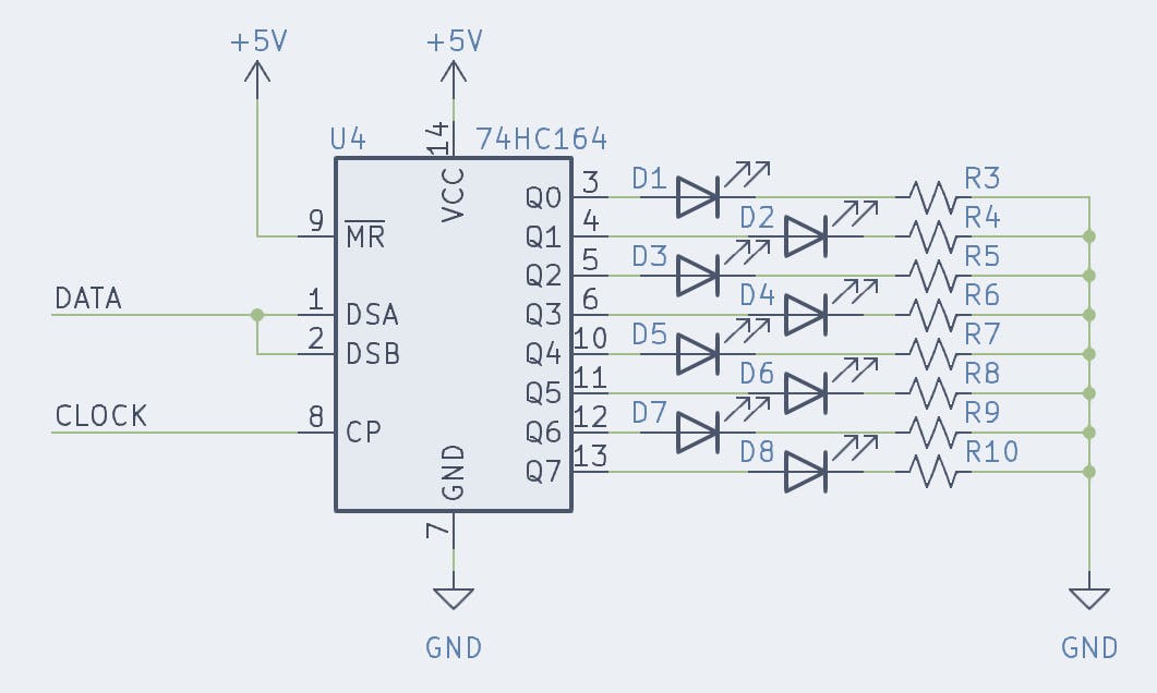
Like in original board, the pumps will be pushed by ULN2803. This chip have 8 darlington transistor pair and can handle 500mA. 2 or 3 pairs can be wired in parallel to better share the current.
[add image]
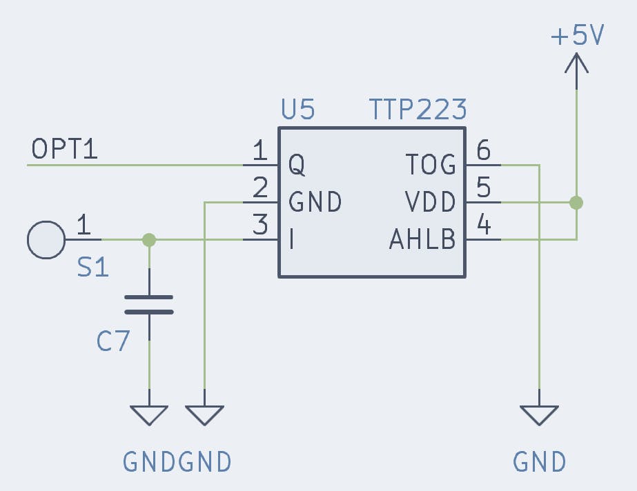
For handle the touches, the idea is to use some TTP223. This is very small (SOT-23-6L package).
This sensor have 2 pins used to configure how the output will behavior. The first one is the AHLB (pin 4). 0 means the output will be high if a touch is detected while if it's equal 1, then the output will be low.
The other pin we should care about is the TOG (pin 6). This pin will toggle the output for each touch if equal 1 or return to original state when touch is removed.
PCB
The PCB must have a custom cutout format to fit the plastic frame. It also have some square cuts to hold the plastic cage responsible for not let the light of one led to bleed to another one.